Diffraction patterns and resolution
In the previous post we traced the passage of light through an Amici roof prism, which required decomposing vectors into components, accounting for phase shifts upon reflection, and then looking at how the waves will be recombined. We can now see that there will be an opportunity for interference effects to degrade the performance of an optical system containing such a prism.
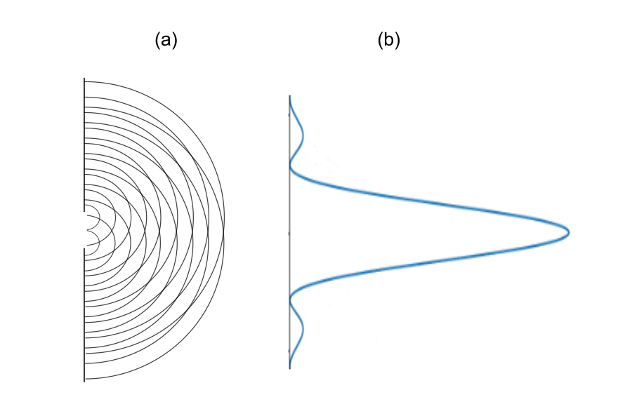
Even without any optical elements to complicate the situation, the propagation of light is affected by phase differences that can accrue in its spatial distribution, and the resulting interference patterns. These are of course the well-known diffraction effects, intrinsic to all waves and which cannot be eliminated. Diffraction stems from the fact that any finite source of waves must produce an ensemble of wavelets that interfere with one another as they expand outwards. This is illustrated in Figure 1(a), which shows waves emanating from an aperture. Here we show just two sets of wavelets arising from the source, each of which spread out in a uniform circular pattern. When we look at different locations beyond the aperture, we see that these wavelets generally travel different distances, meaning that they will arrive with different phases. We can map out the intensity of the light by projecting it onto a screen, and thereby capture all this in terms of a diffraction pattern, as shown in Figure 1(b). The light will form a bright central spot that is wider than the aperture itself, surrounded by lightless areas as well as much fainter regions. This pattern represents the fundamental limit to resolution, because no detail smaller than the width of the main spot can be resolved.
When the light from such a narrow aperture passes through an optical system such as a telescope, the very best that we can hope for is that the instrument doesn’t degrade (that is, broaden) the pattern further, in which case the instrument is said to be diffraction limited. Our goal now is to examine the effect of placing a roof prism between a narrow light source and the projected diffraction pattern.
For an aperture, it is convenient to use a very thin slit illuminated from behind. From a great distance, it might appear immeasurably thin, but if we were to magnify it, we’d find an image that consists of a central line with some finite width, surrounded by fainter bands (it will appear like Figure 1(b) but stretched into a second dimension). Placing a simple Amici roof prism in front of the source will direct the light downward, where we will project it upon a screen, as shown in Figure 2. There are two orientations to consider, as shown by diagrams (a) and (b), with the slit parallel or perpendicular to the roof line orientation, respectively. We will focus on the parallel case (a), and later discuss why the perpendicular one has no effect.

With this orientation, half of the light from the slit takes one path through the prism, and the remaining light goes the other route. In the previous post we focused on two parallel rays that arrive at the prism with the same phase. There is a lot more to manage now, as we must consider the interference corresponding to all the wavelets emanating from the slit. We must account for the phase shifts due to the different wavelet path lengths and the shifts due to the prism surfaces. And that is just for one polarization; we will need to do all of this for all incoming electric field orientations and then add up the results. This is done in detail in section 3 of the technical article. Unfortunately there is no shortcut to working through the calculation.
It should not be surprising that when we combine the two sources of phase shifts – those native to the diffraction pattern and those stemming from the prism TIR – that the destructive interference effects are only going to get worse. It would be incredibly fortuitous if one set of shifts somehow undid the other. After all, there is only one way to add waves to get constructive interference, but many ways to get some amount of amplitude loss. What we find, when the calculation dust settles, is that the net result of having the prism is the introduction of a modulating function (denoted  in the technical article) which multiplies the normal diffraction pattern and distorts its shape, depending on the relative s- and p-component phase shifts. This is animated in Figure 3. On the top left we show the p- and s-components changing in relative phase, and the top right shows how the modulating function responds. The figures on the bottom show the interference pattern, both in terms of the image itself (bottom left) and the intensity versus position (right).

The point of these animations is to depict not only the effect of the phase shifts on resolution, but to show what would happen if we could “dial in” any amount of relative phase shift between the p- and s-components. When these are in-phase, the modulating function becomes highly extended, but when the components are out-of-phase, it becomes narrow, with a low maximum and high minimum. Multiplying this against the nominal diffraction pattern pushes the peak down while bringing the off-peak portions up, which has a net effect of broadening the peak while causing it to lose about 40% of its amplitude as a worst case scenario. The resulting appearance of the slit, as seen in the bottom left, noticeable degrades. But if we can bring the phase shifts together, we can recover the normal diffraction pattern.
A readable account of how early workers, who were using roof prism for military application during the Second World War, came to understand the cause of these effects, is given by A.I. Mahan (“Some Newly Solved and Some Unsolved Problems in Optics.” Journal of the Washington Academy of Sciences 44, no. 6 (1954): 165–94, which can be read online via a free JSTOR account, here. Since they had no recourse to computer animations then, the author constructed a model using strings and matchsticks (which is shown in a photograph in the paper). There were uses for roof prisms which had angles other than 90 degrees between the two reflecting faces, and Mahan describes how for some of them, the effect of phase shift was much worse than what an uncoated binocular prism would produce; some degraded diffraction patterns even appeared as two parallel lines, causing true “image doubling.”
Everything so far has been for the parallel case – what happens if the slit is rotated by 90 degrees, for the perpendicular orientation shown in Figure 2(b)? We need not do any calculations, because we can appeal to symmetry considerations, The light leaving any one portion of the slit is no longer confined to pass through only one of the two paths in the prism. Instead it gets channeled equally through both, so there is no way that any net difference in phase can be acquired. In the Mahan paper, this result was made clear by viewing cross-shaped targets, which produced images of a narrow line bisected by a widened, blurrier one.
Now that we’ve seen how phase shifts collude with the roof prism geometry to cause a degraded image, we turn to the matter of how to fix it. The goal is to somehow eliminate the difference in the p- and s-polarization phase shifts without ruining the TIR. We’ll now consider what we might accomplish by adding one or more dielectric, or insulating, materials between the glass and air.
A First Attempt to mitigate the problem: A Single Dielectric Layer
The simplest way to modify the prism is to add a single, uniform layer (we use terms such as “layer” and “coating” interchangeably) having a refractive index that differs from that of the prism. If the index is less than that of the glass (we will continue to use 1.517 as a nominal value for the index of glass), there will be some range of angles at which we’ll have TIR at the glass/coating interface, and a different range for which it occurs at the coating/air boundary. The transmission angle will be larger than the incidence angle, leading to a reflection at the coating/air interface that is also at a larger angle. This is shown in Fiigure 4(a) below. As we saw in the first post, when we worked out the difference in phase shifts, the more that an angle tends towards the “glancing” case, the smaller the difference in the p- and s-component phase shifts. The same plot showing the effect of angle on the s- and p-polarization phase, and their difference, is shown in (b). The green arrow indicates the reduction in phase offset for large angles, which the coating aims to exploit.

If we intend to leverage this, we will need to address with the fact that not all of the light will make it to the coating/air boundary; there will first be some partial reflection at the glass/coating interface, with the remainder of the light transmitted into the layer and on towards TIR. The situation is significantly more complicated now. The light is again being split into different paths, but here, the paths involve different distances. This means that various different phase offsets will result, with potential interference effects when all the light is added back together. The only knob we will have for tuning such effects, besides the refractive index of the layer, is the layer thickness. But the shifts will also depend on exactly how many wavelengths fit into the path length, so we will be introducing chromatic effects that we didn’t have to deal with before.
This effect is presented in Figure 4(c), where we capture the effect of layer thickness and wavelength in terms of phase thickness, along the x-axis. This thickness is proportional to the physical coating thickness and inversely proportional to the wavelength. We can see that for a value of 90 degrees (a quarter of a wave) the s- and p-polarizations have the same phase. Coating a roof prism in this way would then eliminate our problem. Unfortunately, this solution is only going to hold for a particular wavelength.
So there is some promise to this strategy, but it comes with consequences that need to be addressed. The wavelength dependence is a big one, as is the fact that the angle of incidence at the glass/coating interface must fall within a certain range. If the angle is made larger, the TIR will occur at the glass/coating boundary, which ruins the effect. In a key paper (“Phase Compensation of Total Internal Reflection,” J. Opt. Soc. Am. 56, 1219-1221 (1966)), Mauer showed that in using three layers instead of one, a more robust solution could be obtained.
multiple layer coatings
Although it was an early effort, and modern coatings are more sophisticated, it is worth tracing through the mechanics of how Mauer’s approach works. It is far from trivial. Since we are eschewing the mathematics here, we’ll aim for a descriptive overview of what Mauer was trying to do. Figure 5(a) illustrates some of the paths that light will take through a three-layer structure between glass and air. Note that there are multiple reflections which must be accounted for (there are secondary reflections and beyond as well, which would be difficult to track “by hand” but which the transfer matrix method used in the technical article handles easily). Diagram (b) shows the resulting s- (red) and -p-polarization (blue) phase shifts. There is a fairly broad range of thicknesses for which the phase shifts are very nearly equal, pointing to a potential design space. These curves replicate those in Figure 2 of the Mauer paper.
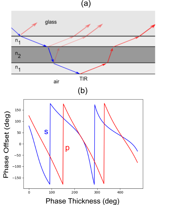
Figure 5. (a) Schematic of the three layer phase coating proposed by Mauer. Diagram (b) shows the final phases for the reflected light having p- (blue) and s-polarizations (red). There is a range of thicknesses over which the phase offset can be tuned very close to zero. This plot reproduces the results shown in Figure 2 of the Mauer paper.
It should be apparent that such a coating is an improvement, but is still not going to function very well if we wish to remove the phase offset across the visible range, because the region where the two curves come together is fairly small. In going from violet to red, the phase thickness will change by a factor of two or so, but here, we see a range that is only about 10%.
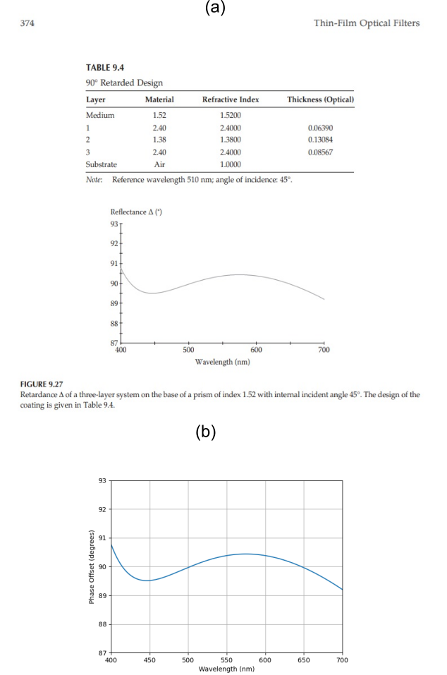
As one might expect, a better solution can be pursued by adding even more layers. Such an approach is cited in a U.S. patent filed by Ito and Noguchi in 2001 (US6304395B1). A range of recipes are provided for nine-layer coatings which are effectively three sets of the Mauer trilayer. We can easily extend the approach used to calculate the phase offset to as many layers as we like, and to make the independent variable the wavelength instead of phase thickness. Python code was written to do the transfer matrix analysis for up to a nine-layer coating, and is provided below. It includes, as a sanity check, a calculation for a three-layer retarder as described and shown in Figure 9.27 of Macleod (Macleod, H.A. (2021) “Thin-Film Optical Filters: Fifth Edition (Series in Optics and Optoelectronics),” 5th Edition, CRC Press.) Results for this are shown along with the code below.
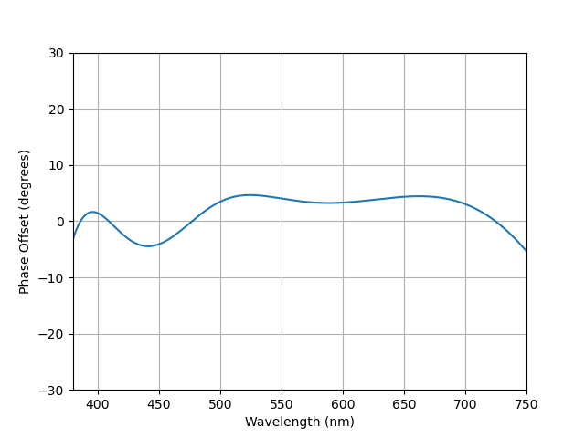
Figure 6 shows the calculated phase offset for light within glass of index 1.518 incident at an angle of 49 degrees upon a nine layer coating having the following optical thicknesses (in nm) listed in their order from glass side to air side: 33.27, 105.53, 54.57, 163.13, 75.76, 96.81, 118.5, 223.14, and 126.15. The corresponding refractive indices are 2.055, 1.388, 2.055, 1.4693, 2.055, 1.4693, 2.055, 1.388, and 2.055. The specific thicknesses were found by running a simple optimization routine which looked for minimal phase shift over the bandwidth. As can be seen, the variation in phase offset over the entire visible spectrum remains within 5 degrees or so of zero.
It should be noted that other solutions have been proposed, although it is not clear if they have been implemented. An example is due to Rabinovitch and Toker. (Rabinovitch, K. and Toker, G. (1994) “Polarization effects in optical thin films,” Proceedings of SPIE, 2253(1), 89-102.) They describe a dielectric trilayer further coated with silver. This means that the TIR effect is sacrificed, of course, so some transmission loss is taken in a trade for elimination of the phase effect.
Another reference by these same authors (Rabinovitch, K. and Toker, G. (1994). “Genetic algorithm and thin-film design,” Proceedings of SPIE, 2262(1), 163-174.) is also worth a read. They outline an optimization method they have used to winnow through the very large design space that must accompany the use of multilayers. Choosing the nominal refractive indices and layer thicknesses for sophisticated multilayer designs from first principles would be a Herculean task, but fortunately one need not attempt it because an accurate model can be explored in a systematic way to find the optimal design.
Conclusion
The goal here was to try to make the origin of the roof prism problem a bit more intuitive, and to illustrate what a phase coating strategy can look like. Certainly there exists an entire world of trade secrets pertaining to modern coatings which will not be shared via patents or publications. This is expected, if inconvenient, since optics manufacturers would be understandably loathe to share proprietary information in such a highly competitive market. Because of the paucity of information on this curious and important problem, I am especially interested in any technical content which has escaped my attention so far.
I also solicit any and all comments, complaints, and questions via hurbenm at gmail.com.
A few more odds and ends related to this issue can be found at Chromatic Effects of Coated Roof Prisms on Polarized Light and Polarization effects in optical thin films. For a list of references, see Technical References for Roof Prism Resolution Loss, Phase Coatings, and Related Topics.
Code
# Wavelength Impact on Phase Coatings: 9-layers - MJ Hurben Oct 2024
import numpy as np
import matplotlib.pyplot as plt
d2r = np.pi / 180  # Degrees to radians factor
na=1 #Index of air

option='3layer' # choose '9layer' or '3layer' or 'none'

if option=='9layer':
    ang=49 # Incidence angle in glass
    ng=1.5181 # Index of glass
    # n and d arrays are from glass to air; d are optical thicknesses in nm
    n=np.array([2.055,1.388,2.055,1.4693,2.055,1.4693,2.055,1.388,2.055])
    d=np.array([33.27,105.53,54.57,163.13,75.76,96.81,118.5,223.14, 126.15])

if option=='3layer': # Reproduces Figure 9.27 of Maccleod Thin Film Optical Filters, 5th ed
    ng=1.52
    n=np.array([ng,ng,ng,ng,ng,ng,2.4,1.38,2.4])
    refwl=510
    d=np.array([10,10,10,10,10,10,0.06390*refwl,0.13084*refwl,0.08567*refwl])
    ang=45

if option=='none': # No coating check: will give flat, non-zero response
    ng=1.52
    n=np.array([ng,ng,ng,ng,ng,ng,ng,ng,ng])
    d=np.array([10,10,10,10,10,10,10,10,10])
    ang=45

def PS(nva,dva,wl,ang): # Phase Shift calculation

    def M(nA,nB,mode,ang): # Transfer matrix for interface
        aRad=ang*d2r
        g=1-nA**2*np.sin(aRad)**2/nB**2
        if nA*np.sin(aRad)<nB:
            cosT=np.sqrt(g)
        else:
            cosT=complex(0,np.sqrt(-g))
        if mode<1: # S-Pol
            r=(nA*np.cos(aRad)-nB*cosT)/(nA*np.cos(aRad)+nB*cosT)
            t=1+r
        else: # P-Pol
            r=(nB*np.cos(aRad)-nA*cosT)/(nB*np.cos(aRad)+nA*cosT)
            t=nA*(1+r)/nB
        d=1/t
        offd=r/t
        m=np.array([[d,offd],[offd,d]])
        return m

    def P(L,n):  # Transfer matrix for propagation
        L=L*n*2*np.pi
        v=complex(np.cos(L),-np.sin(L))
        p=np.array([[v,0],[0,v.conjugate()]])
        return p

    angles = [ang]
    next_angle = np.arcsin(ng * np.sin(angles[-1] * d2r) / nva[0]) / d2r
    angles.append(next_angle)
    for i in range(0,len(nva)-1):
        next_angle = np.arcsin(nva[i] * np.sin(angles[-1] * d2r) / nva[i+1]) / d2r
        angles.append(next_angle)
    angles = np.array(angles)
    L = dva * np.cos(angles[1:] * d2r) / nva

    for md in range(0,2):
        W=M(nva[8],na,md,angles[9]) # Interface of last layer and air
        for i in range(8,-1,-1):
            W=np.matmul(P(L[i]/wl,nva[i]),W)
            if i>0:
                W=np.matmul(M(nva[i-1],nva[i],md,angles[i]),W)
            else:
                W=np.matmul(M(ng,nva[0],md,ang),W)  # Interface of glass and first layer

        if md==0:
            rs=W[1,0]/W[0,0]
            phases=np.arctan(rs.imag/rs.real)/d2r
        else:
            rp=W[1,0]/W[0,0]
            phasep=np.arctan(rp.imag/rp.real)/d2r

    pdd= phases - phasep
    if pdd<0:
        pdd=pdd+180
    if pdd>135: # To allow the Macleod plot to be continuous, otherwise use 180
        pdd=pdd-180
    return pdd

plt.grid(True)
wls=[]
pdds=[]

for wl in range(400,701,2):
    pdd=PS(n,d,wl,ang)
    wls.append(wl)
    pdds.append(pdd)
plt.plot(wls,pdds)
plt.xlim(400, 700)
plt.xlabel('Wavelength (nm)')
plt.ylabel('Phase Offset (degrees)')
plt.show()
Results from 3-layer checkout: