
Many binoculars utilize roof prisms to keep the light along a single optical axis, making for a more compact shape. But the novel geometry of the prism’s reflecting surfaces creates a subtle interference effect which reduces the binocular’s resolution. The only way to mitigate this problem is to use specialized coatings on the roof surfaces. An explanation of the performance degradation, its root causes, and how some coating solutions work, are discussed in several previous posts. A full technical paper is at this link: The Physics of Roof Prisms and Phase Coatings; for a less technical treatment, see: The Physics of Roof Prisms and Phase Coatings, Simplified: Part I, The Physics of Roof Prisms and Phase Coatings, Simplified: Part II, and The Physics of Roof Prisms and Phase Coatings, Simplified: Part III.
As discussed in the above references, the details of the “phase coatings” used by optics manufacturers are generally kept under wraps. The proprietary nature of such trade secrets within a highly competitive industry results in a paucity of information on the designs, compositions and deposition thicknesses. Technical references include an early paper by Mauer (“Phase Compensation of Total Internal Reflection,” J. Opt. Soc. Am. 56, 1219-1221 (1966); see the links above) that spelled out a basic strategy for using multilayer structures that could reduce or eliminate the phase shift between the s- and p-components of the light upon total internal reflection (TIR), and a patent by Ito and Noguchi (US6304395B1) which details several nine-layer designs. It is not difficult to perform an analysis similar to that of Mauer for the larger multilayer structure and show that it provides improvement in terms of a wider spectral range over which the phase offset can be minimized; the code for doing just that is included in Part III alluded to above. Modern coatings are certainly leveraging such multilayers, and perhaps even more sophisticated approaches. More on that later.
Although any modern roof prism device is going to have phase coatings, the topic of how to discern their presence remains an interesting one. A method for doing this was briefly outlined in an oft-cited, 1988 reference on phase coatings from Zeiss, authored by Weyrauch and Dörband. (Having only ever seen a scanned PDF version of this article in German, I used OCR and AI to develop an English translation, which is attached here.)
Their simple test for the presence or absence of phase coatings involves placing the binoculars between a pair of polarizers that are either parallel or “crossed” (at right angles). Provided that at least one set of polarizer axes are parallel to the prism roof line (the projection of the roof prism line on a plane perpendicular to the optical axis), the amount of light transmitted will be different for the parallel or crossed conditions in a way that depends on the presence or absence of the coatings. (The need to line up a polarizer parallel to the roof is a requirement we will discuss below). Specifically, an uncoated roof prism will cause the most light to pass when the prism is placed between crossed polarizers, while a prism with phase coatings will pass more light when placed between parallel polarizers.
The authors do not provide even one word of explanation as to why this test works, just as they do not provide any significant details on degradation mechanism itself or the design strategy of the phase coatings. In order to explore why their procedure is valid, I performed an analysis of the polarization changes using the usual Jones calculus approach. The details were worked out for both Abbe-König (AK) and Schmidt-Pechan (SP) designs in order to verify that the result holds for both cases, and it does. (The Zeiss paper does not mention different prism designs.) For simplicity, we will trace through the AK case here.
Figure 1 shows the coordinate system (green), reflective surfaces (maroon), surface normal vectors (blue) and light path (black) for one of the two paths through the prism. The two angles  and
and  can be chosen, but if the output beam is to be parallel to the input,
  must be the sum of the other two angles, as is easy to show from basic geometry. Based on the scant A-K diagrams available from optics companies, the most popular approaches seem to be values of 30, 0, and 30 degrees or 30, 7.5, and 37.5 degrees.
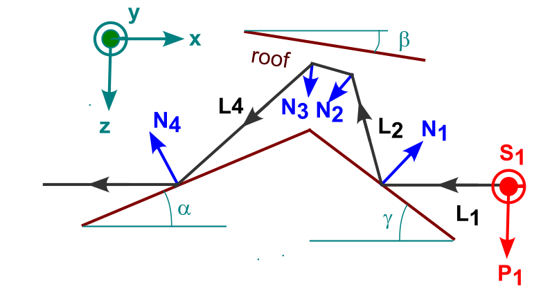
The next step is to write out the normal vectors explicitly as well as unit vectors that capture the directions of the light at the various sections in the path. Once those are determined, the unit vectors for the polarization directions are easy to write down, and then the rotation Jones matrices can be constructed. The process is exactly the same as that used in the technical paper for the Amici prism, but with two additional, non-roof surfaces.
Specifically, the approach here used angles of 30, 7.5, and 37.5 degrees, expressed in radians using a,b, and g in the Python code, with the four normal vectors then being given by:
N1 = np.array([np.sin(g), 0, -np.cos(g)])
N2 = (1/s2) * np.array([-np.sin(b), -1, np.cos(b)])
N3 = (1/s2) * np.array([-np.sin(b), 1, np.cos(b)])
N4 = np.array([-np.sin(a), 0, -np.cos(a)])
L1=np.array([-1,0,0])
The variable L1 is the direction of the incoming light, along the negative x-axis, and s2 is  . With these definitions, the remainder of the analysis follows in a straightforward manner. For the full code, see Polarization-Based Testing of an Uncoated Roof Prism.
Figure 2 shows a series of polarization plots based on this analysis. The incident light is linearly polarized in the vertical (z) direction, which corresponds to the projected direction of the roof line. After the first reflection, the polarization is maintained, because the incoming light lies entirely in p-direction for this first surface (in Figure 1, this is the surface with normal vector N1.) The second reflection is at the first roof surface, where both p- and s-components are present, and so with the phase shift, the results after reflection are elliptically polarized. The third reflection is off the next roof surface, and the fourth and final reflection, giving the output, comes of the final, non-roof surface defined by N4. The arrival of elliptically polarized light in these cases results in more elliptically polarized results. What is critical here is the orientation of the ellipses after the final reflection, which comprises the output.
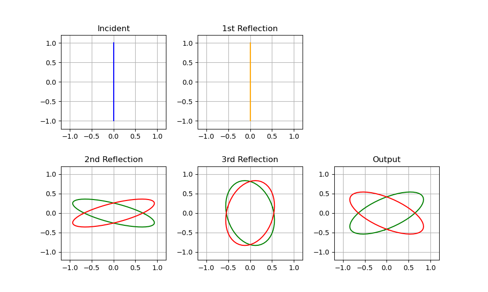
The final polarizations are elliptical but inclined more to the horizontal. If this light is viewed through a polarizer, oriented along either axis, we’ll see more light passed for the “crossed” polarizer case. Note that the vertical and horizontal field components will differ by a factor of only about 50%, so the intensity will differ by a factor between two and three. Hence, with no phase coating present, more light is passed through crossed polarizers than for parallel polarizers. I explore this experimentally in the post Polarization-Based Testing of an Uncoated Roof Prism.
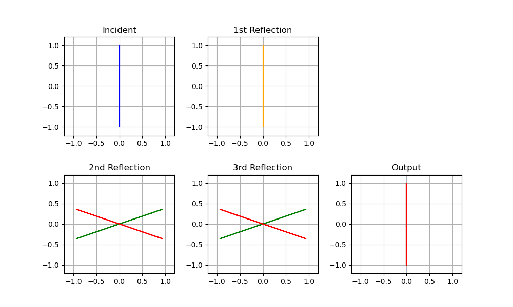
In Figure 3 we show the calculated results when phase coatings are applied to the roof surfaces. The incoming light has both p- and s-components upon arrival at the roof, but with no phase shift, the reflected light remains linearly polarized. Since the entire set of rotations delivers outgoing light that is parallel to the incoming light, we expect the entire series of reflections must “straighten out” the polarizations, and that is exactly what the calculations leave us with. In this case, parallel polarizers will pass all of the incoming light, and crossed polarizers will pass nothing.
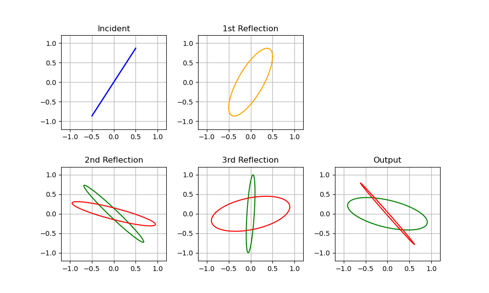
The requirement that the initial polarization be parallel to one set of polarizers can be understood if we look at what happens with some other incoming polarization states. This is shown in Figure 4, where we have chosen the case of no phase coatings. As can be seen, the two paths lead to different inclinations for the final polarizations states. With phase coatings, the two states will be the same, but will still be elliptically polarized and inclined. The conclusion is that such a geometry is not amenable to forming a clear conclusion using the two polarizer orientations. What is critical is that the light reflecting off of surface 1 remain linearly polarized, and if the incoming linear polarization is either parallel or perpendicular to the roof line, that will hold.
Now that we have explained why the dual polarizer test works and why the restrictions are necessary, we mention another effect that are apparent during such testing, namely, pronounced chromatic effects which vary with the orientations of the prism and two polarizers. It is curious that Weyrauch and Dörband say nothing about this, as it is one of the most striking results and is immediately apparent. Moreover, users of roof prism optics in the field will quickly notice that having polarized glasses between their eyes and the eyepieces can produce startling results when the binoculars are receiving naturally polarized light, such as that arriving from certain areas of the sky or from reflections.
The easiest way to see these chromatic effects is in a controlled fashion is to use a uniform source of polarized white light and to look through the optical device in reverse with a polarizing filter placed over the objective lens. One can then either rotate the polarizing filter, or the binocular, or both, in order to scan through all possible ‘input’ and ‘output’ polarization directions. LCD screens are polarized, so they make a convenient source. Figure 5 shows a simple setup used to explore these effects. A pair of binoculars is mounted so as to face away from the screen. In this effort an inexpensive polarizing sheet was attached with tape to the body so as to cover one of the objectives.
Some typical results are shown in Figure 6, for which the orientation of the polarizing sheet was changed and the resulting image was photographed. The line indicates the relative orientation of the polarizer sheet. For the leftmost image, the polarizer is parallel to the polarization direction of the screen, as well as the axis of the roof prism.
The pattern and its angle dependence is clear. Moving from left to right, the polarizer is rotated clockwise. Initially, the line demarcating the two halves of the prism is barely discernable. Soon the line jumps out, with a marked blue color on the top-right and red on the bottom-left. The color pattern remains but the image grows darker until reaching a minimum level of light transmitted through both sides when the polarizer is at 90 degrees to the source polarization (the “crossed” condition). In the rightmost image, after moving somewhat past this limit, the colors return, but have been inverted. Continuing to turn the polarizer will eventually bring us back to the left-most image. Similar behavior can be seen by rotating the optics relative to the screen.
Other roof prism binoculars on hand showed comparable results, although the particular colors were somewhat different in each case, indicative of different coating designs. When uncoated prisms were tested, no such color patterns were seen. This is as expected, because there is no mechanism in the total internal reflection mechanism alone that would have a wavelength dependence for typical prism glass. Only the presence of coatings and TIR can account for these effects.
The change in color with orientation should be familiar to anyone that has examined a birefringent material. Such materials possess different refractive indices along different crystalline axes. Thin layers of such materials will cause differing amounts of polarization rotation for different wavelengths, leading to the production of interference colors when polarized light is passed through them and then viewed with a second polarizer. Even a piece of cellophane examined in this way can produce vivid colors, because its index of refraction is not isotropic.
That birefringent materials produce colors when examined with polarizers is extremely useful in the field of crystallography. The color of light transmitted through a sample depends upon the orientations of the polarizers as well as the sample thickness and its birefringence, which can be quantified as the difference in the fast and slow refractive indices. Such color, and its dependence on the sample parameters, is captured in terms of the Michel-Lévy chart, a modified version of which is shown in Figure 7.
This plot was calculated in Python using an approach spelled about by Sørensen, B.E. (2013). (A revised Michel-Lévy interference colour chart based on first-principles calculations. European Journal of Mineralogy, 25, 5-10.) Along the x-axis is B, the birefringence, defined as the difference in refractive index between the fast and slow axes, and along the y-axis is t, the thickness of the material in microns. The color which corresponds to a given point will be obtained when the linearly polarized light falls along the fast axis, while upon a 90 degree rotation, the complimentary color will be obtained. It isn’t hard to set up a modified model based on the above chart that functions for any orientation of the polarizers and crystalline axes, which then shows how the orientations move one through the complimentary colors. An example is shown in Figure 8 below.

While the changes of color in coated roof prisms appear to suggest a similar effect, that does not indicate that birefringent materials must be involved (see below). It would certainly seem like a possible strategy for tuning out the TIR phase effect, because multilayers have been developed which can function as achromatic waveplates: they can be tuned to cause a specific phase shift over the entire visible spectrum range. See, for example, Jen, YJ., Lakhtakia, A., Yu, CW. et al. Biologically inspired achromatic waveplates for visible light. Nat Commun 2, 363 (2011). That being said, a similar effect can result with isotropic films combined with TIR.
We already know that the s- and p-polarizations get different phase shifts upon TIR. That effect has no wavelength dependence, so the color effects cannot be produced from simple TIR alone. With the introduction of any coating, however, wavelength will play a role, because of the interference effects from the multiple layer boundaries. This has no polarization dependence, of course, but when the final layer in a stack of coatings includes a TIR effect, we have both effects present together in the system. Working through a simple transfer matrix model brings the polarization dependence in via the interface matrices, and the wavelength dependence through the propagation matrix. Placing such a structure between a pair of polarizers now provides a mechanism for producing polarization-dependent colors.
I am currently developing a Python model to map out the expected color changes with angle based on a multilayer approach such as that proposed by Mauer for phase coatings. It is still a work in progress. I have yet to find any technical references that flesh this out specifically for coated roof prisms, so if you know of any, please email me at hurbenm at gmail.com. One goal of the model is to produce plots of the color versus angle space that can be compared with experimental results. The specific color trajectory taken through the orientation space might lead to some conclusions about the coating details. I also plan to include the capability to include different multilayer recipes on each of the two surfaces, as well as anisotropic refractive indices to account for birefringence, and combinations of dielectrics topped with a metal layer.
It continues to astonish me that such ubiquitous devices produce these novel effects and yet have gotten so little technical attention to speak of.
A. Weyrauch, B. Dörband: P-Belag: Verbesserte Abbildung bei Ferngläsern durch phasenkorrigierte Dachprismen. In: Deutsche Optikerzeitung. Nr. 4, 1988.
G. Joos: Die Bildverschlechterung durch Dachprismen und ihre Behebung. In: Zeiss Nachrichten. 4, 1943, S. 9.
Thank you. I was aware of those papers. I’ve not bothered with the Joos paper as it likely cannot speak to modern coating technology, and it precedes the Mahan papers which are remarkably thorough, and seem to capture the state of affairs shortly after WWII. As for the Weyrauch paper, I’d struggled through the German previously, but now with your prompting, I reran a scanned PDF through an OCR engine and then asked the latest Claude Opus AI to translate and correct the typos. Unfortunately, as I had surmised earlier, that paper provides absolutely no detail on the multilayer strategy, compositions, thicknesses, and so on. It also eschews any mention of the chromatic effects as revealed by a pair of polarizers.