
Introduction
The reflection of light at a boundary between media with different refractive indices is one of the most common and important phenomena in all of physics. Depending on the specific index values, the angle of incidence, and the polarization of the light, different outcomes are possible, including partial reflection and transmission, total internal reflection, evanescent waves, and various phase shifts which can lead to complex optical effects. We come face-to-face with all of this when treating practical problems such as phase correction coatings in roof prisms or oblique incidence on an interface.
Understanding the behavior of light at an interface means carefully accounting for the boundary conditions on the electric and magnetic fields, and how they manifest for different refractive indices, propagation angles, and polarizations. The analysis is fairly straightforward, and produces a set of results, the Fresnel equations, which are of great practical use.
There is, however, a novel ambiguity that crops up in the Fresnel derivation, and is related to the freedom we have in choosing how we define our field directions. Essentially, there are two ways we could go, and this is often not discussed explicitly in textbooks or in the literature—and both conventions do get used. For example, the standard undergraduate text Optics by E. Hecht uses one approach, while another classic, Introduction to Electrodynamics by D.J. Griffiths, uses the different strategy. As a result, their formulas for the reflected electric field differ. Many readers or students are not aware that any ambiguity is even lurking here.
Generally this escapes attention because as long as we pick one approach and stick with it (and avoid scrutinizing some of the implications) either method will be fine. After all, the point of the analysis is often to get the reflection and transmission coefficients R and T, which are the same for both approaches. But there are two problems that can crop up: First, as we will see shortly, each of these sign conventions will yield a non-intuitive result that is most clearly seen when considering a limiting case (that is, for either normal incidence or grazing incidence). Second, special care must be taken when trying to combine results coming from different workers who have been using the two different approaches. Indeed, this is exactly what will happen if you work through the original papers on (1) roof prism phase shifts and (2) the coatings which can mitigate the problem, which each used a different convention. Hence you may need to do some detective work as the choice in convention is rarely made explicit.
In this post, we will demonstrate the ambiguity and the unsatisfying results it causes. We will then derive the two sets of Fresnel equations that correspond to these different conventions and compare their predictions. Finally, we will suggest a simple modification which makes the entire issue go away.
The final impetus I needed to write this all up comes courtesy of a reader who went through my derivation of the Fresnel equations here (largely the same derivation as what follows) and noted that the results did not accord with common sense expectations for a limiting case. And this reader is right. It is a problem that simply does not get much attention, so if and when you do run across it, it can be very troubling.
The Problem
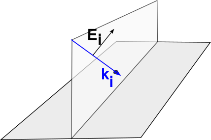
Let’s consider the specific case of light moving through a “slow” medium such as glass, and meeting an interface with air, in which the speed of light is larger. The incident direction is captured by the vector ki, and we will assume that the incoming light is linearly polarized and that the incident electric field (Ei) lies in a plane that is normal to the interface. This is called the “p-polarization” case (also known as “TM” for “transverse magnetic”). The situation is shown in Figure 1.
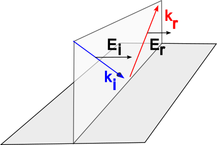
Our next question is this: what shall we take as the direction of the electric field for the reflected light? We will need to make a decision about this, because to understand exactly what happens upon reflection and transmission, we must enforce the boundary conditions on the electric and magnetic fields. (Keep in mind that by choosing the E direction, we will have also fixed the B direction because E crossed onto B must give the propagation direction.) If we are thinking about the light coming in at an angle at which total internal reflection (TIR) is about to occur, then it would make sense that the electric field for the reflected light (Er) should also be pointing “upwards” just as it is for the incoming light. This is shown in Figure 2, where the reflected direction is indicated by kr. Keep in mind that there is no phase shift upon reflection in this case.

This seems correct, but think about what this means if we now make the angle of incidence steeper. That is, think about what Figure 2 is telling us if the light were coming in nearly perpendicular to the boundary. It says that the electric field upon reflection will be inverted relative to the incoming light. We don’t expect that to be the case here, as we are moving from a slow into a fast medium. To see just how obnoxious this is, consider if the electric field polarization had been in the “s” direction: that is, a “TE” polarization direction, in which the electric field is parallel to the boundary. This is shown in Figure 3. In that case, there is no problem as we change the incidence angle. When the light is falling straight down, the reflected field points parallel to the incident field, as we would expect.
Going back to the problematic “p” case in Figure 2, we could have chosen the electric field direction for the reflected light to be in the other direction, in which case, this problem at normal incidence would go away. This means we would choose the convention shown in Figure 4 below, which we will call the “Case II” approach. So now, we feel better about what happens at perpendicular incidence, but then when we go in the other direction, with the angle getting larger, we are left with the unappetizing idea of the electric field orientation flipping. It seems that in choosing either Case I or Case II and trying to apply the convention consistently, that we just cannot win.

So we must pick our poison, and decide which of these two results is less bothersome. And this is where everyone makes their choice, with some texts taking one tack and the others choosing the opposite, usually without even pointing out the conundrum. Below, we will describe a third approach which resolves this problem, but first, we will go through the derivation for the Fresnel coefficients, so that we have concrete expressions which capture the issue.
Fresnel Equations for Case I
We consider light incident from the left that is reflected and transmitted at a boundary. Because there is now a non-zero angle of incidence, we need to be clear with the nomenclature for the geometry. We must keep in mind that light consists of paired oscillations in the electric and magnetic field, each of which is perpendicular to the propagation direction, which we capture by specifying the vector k. This is to say that the vectors E, B, and k are each at 90 degrees to the other two, and they satisfy the right-hand rule, such that if your finger starts by pointing along the E direction, then curl in towards B, your thumb will indicate the k direction.
In Figure 5 (a) we begin with the coordinate system and directional definitions. The directions of light are indicated by the arrows, with material “1” on the left and material “2” on the right. Incident light (blue) is reflected (red) and transmitted (green).
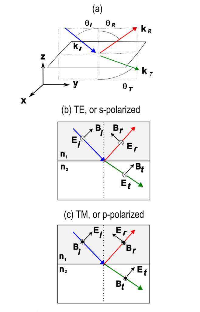
In diagram (b) we show the case of “s” polarization, in which the magnetic field B lies in the plane of propagation (that is, in the y-z plane). In that case the electric field E must lie in the x-z plane. In diagram (c) we show the “p” polarization scenario, where the electric field is now in the plane of propagation instead. These two cases must be treated independently and will result in different expressions for the reflection and transmission coefficients. Note that in both cases the incident and reflected angles will be the same, while the transmitted and incident angles will be related by Snell’s law. That is:


We will once again assume that the incident light has an electric field strength of 1.0, and that the reflected and transmitted amplitudes are given by r and t, respectively. Our goal is to find expressions for these coefficients that depend on the refractive indices and angles. We’ll start with the s-polarization case first. The boundary conditions for the fields here are quite simple: all of the components of B and E must be continuous. This comes from simply enforcing Maxwell’s equations at the boundary, and we are assuming that the materials are simple dielectrics with no difference in magnetic properties. We can therefore write for the electric field:

or

Where
 and
and 
As for the y-component of the magnetic field, we can see from the diagram that

For an electromagnetic wave we must have  , so this can be written as

But since we can eliminate t and solve for r, which gives, for this case of s-polarization:

And then the expression for t is immediately found to be:

For the case of p-polarization we take the same approach, but we now have:

And because this is

All we did was enforce that the magnetic field be continuous across the boundary, as must be the y-component of electric field, so we have:

Or

It is trivial to solve for the coefficients as we did above, giving:

And

The expressions for rp, rs, tp, and ts are the Case I Fresnel equations.
Note that an unhappy result greets us when we consider the limit in which light is incident from directly above, along the z-direction, and all the cosine terms go to 1. In that case:

This is very obnoxious, because it seems that the s- and p-polarizations should give the same result; after all, there is no difference between these two polarization directions when the incidence is normal, and nothing should break the symmetry between them.
Now, in the limit that incidence is grazing, the incident and reflected cosines go to zero, while the transmitted cosine remains non-zero (this is assuming of course that the transmitted medium has a larger index and there is no TIR). In that case

And here we do expect both to have this negative sign because we know that the electric field direction is reversed upon reflection. The results agree and we are happy. In the case that the reflecting medium has a lower index, and we are incident at the TIR angle, then we would set the transmission cosine to zero, yielding

This also makes sense. So we are seeing that our Case I approach is good for “large enough” incidence angle but a problem when they are small.
Fresnel Equations for Case II
What changes if we use the other convention? Nothing about the s-polarization analysis needs to be altered. The only thing we need to do is call out the new directions for the p-polarization electric and magnetic fields upon reflection. The change is shown in Figure 6. Compare this to Figure 5(c) above.

The derivation for the p-polarization for this new approach follows the same lines. We begin with magnetic field, where a sign change affects the reflected part:

And because this is

Again, all we did was enforce that the magnetic field be continuous across the boundary, as must be the y-component of electric field. Here the reflected electric field gets a sign change compared to what we had gotten above, so

Or

It is trivial to solve for the coefficients as we did above. To indicate that the Case II coefficient for p-polarization is different, we denote it as r’:

and the transmission coefficient is unchanged:

So now we can see that in the limit of normal incidence, all of the cosine terms go to 1 and we obtain:

Of course, at larger angles we have the other problem crop up. If the second index of refraction is larger, we have no TIR and we can set the incident angle cosine to zero, and we get:
 while
while 
This is obnoxious. Meanwhile for the case of TIR, we would get the equally annoying result:
 while
while 
It is instructive to plot the r expressions for both polarizations as a function of angle for the two different scenarios. These are shown in Figure 7 below.
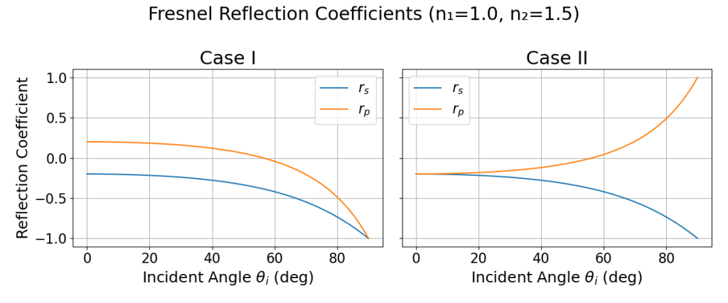
Keep in mind that if all we care about are the reflection and transmission coefficients R and T, which come from squaring r and t, respectively, then none of this matters. Both Case I and Case II yield identical results.
How Shall We Fix This?
We should first note that the p-polarization is the field orientation that gives zero reflection at the special case of incidence at Brewster’s angle. This is a natural point at which we should dissect our problem. Consider that for our case, Brewster’s angle is 56.3 degrees. Below this, the curve for Case II is appropriate, but above it, the curve for Case I is. We can then simply say that we should choose different conventions for the two regimes on either side of Brewster’s angle. This means we could simply write, for the case of n2 > n1:
 if
if 
This result is shown in Figure 8 below.

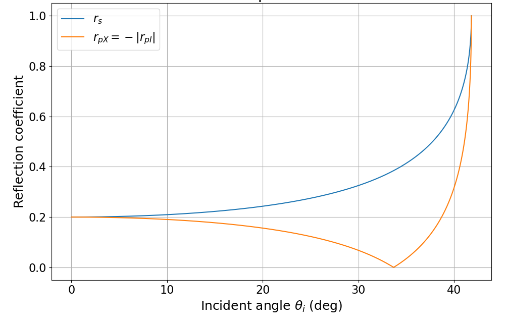
We must be careful not to apply this when n2 < n1 however. In that case, we will want r for both kinds of polarization to always be positive up until the TIR angle, as there is no phase shift. So in that case:
 if
if  .
.
The results are shown in Figure 9. Again we have something that makes sense at both endpoints.
What about larger angles, above the TIR threshold and out until 90 degrees? Here because there is TIR, we expect r = 1 for both polarizations. There are however, phase shifts upon reflection which one needs to take some care with; see this post.
It should be noted that a similar approach is developed by Oh and Vandervelde (see reference below). They describe the inclusion of an additional parameter they call m which can be either +1 or -1.
References
E. Hecht, “Optics”, 5th ed., Pearson (2016).
D.J. Griffiths, “Introduction to Electrodynamics,” 4th ed., Cambridge University Press (2017).
M. Oh and T. Vandervelde, “Bridging the gaps between different sign conventions of Fresnel reflection coefficients towards a universal form,” 2020 IEEE 63rd International Midwest Symposium on Circuits and Systems (MWSCAS), Springfield, MA, USA, 2020, pp. 707-713, doi: 10.1109/MWSCAS48704.2020.9184440.
regarding your post from 14 Dec 2024. You make a statement in the text that t12 = t21. That is obviously incorrect, unless n1 = n2.
Thank you. Good catch. I dropped the refractive indices. It has been corrected.